 Modern
Projects
Modern
Projects
Modern
Projects
This page is dedicated to the various proposals that have been generated in the drawing office at Akohniçe over the years.
All text and graphics (c) Norman Clubb 2012-2015
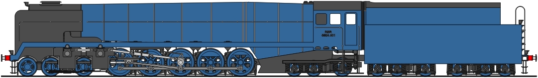
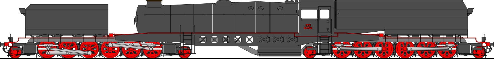
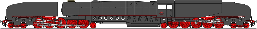
Class 565A Triple-Expansion Compound Goods Locomotive (1997)
The 565A was a forerunner to the 755A proposal, which in turn led to the highly successful 655A. Never mind that twelve-coupled wheels are no rarity on the RSR, it seems that in this design, five coupled axles was a holy maximum number and to exceed it was kind of heresy. A new development was the three-crank six-cylinder triple-expansion compound layout. To accomodate this arrangement, with the inside cylinders driving the cranked first coupled axle, the high-pressure cylinder had to be placed too far forward to be carried by an orthodox four-wheeled front bogie, hence the six-wheeled one seen here. The size of the firebox necessitated six wheels at the rear, too. The boiler dimensions are similar to those of the 655A, except that the firebox is somewhat larger (as is the grate area) and the boiler barrel slightly shorter. Perhaps the parameters applied to the gasflow modelling program were decided upon in a hurry. The trailing and tender bogies are noticeable for the linkage connecting adjacent axleboxes, obviating the need for a less stable separate pedestal at the end of the bogie frame.
A number of flaws are immediately visible in this design. Only five axles (disregarding the booster) out of a total of eleven are available for adhesion. The assignment of the cylinders to the different stages of expansion is not clearly defined in the accompanying documentation, which suggests that the design was not properly thought through. The tender coal space is disproportionately large at the expense of the water capacity, although no water scoop is visible. (The RSR began installing water troughs in suitable locations at the end of the 1990s and plans for this work must already have been known about when this design was drawn up.)
Class 635A Triple-Expansion Compound Goods Locomotive (1997)
The locomotive shown above was inspired by a Friend of the RSR who describes himself succinctly as an X-X-0 fan. In other words, there should be no carrying wheels under the firebox. Since the RSR already has (or had) 4-4-0s, 4-6-0s, 4-8-0s and 4-10-0s, the obvious next step was to a 4-12-0. To keep the length of the boiler in bounds the Doherty layout was abandoned in favour of a three-cylinder arrangement, triple expansion being retained. The lower power output was fully attuned to the more modestly dimensioned boiler. Other classical modern features include poppet valves, twin Lempor exhaust and gas producer combustion system.An innovation of the 635A was the variable-port poppet valves. It is the normal situation with a reciprocating steam engine that the cylinder pressure is highest at the start of the power stroke and that after closure of the admitting valve (or poppet inlet valve) - this is what is referred to as the cutoff - the steam continues to do work by expansion. Thus the cylinder pressure falls continuously until the piston reaches the end of its stroke (or rather when the exhaust valve opens). Longer cutoffs are normally required for starting or working hard at low speed. The cams of the 635A's valve gear were configured to permit (a) a variable rate of inlet valve closure and (b) a supplementary admission of steam later in the piston stroke. Thus the torque is much more even throughout the revolution of the driving wheels, reducing the tendency to slip and permitting a lower factor of adhesion. The estimated weight of the 635A was 127 tonnes total and 108 tonnes adhesion. With conventional valve gears and assuming an adhesion factor of 3.8, the maximum tractive effort that could be brought to bear without excessive slipping would be some 28.5 tonnes. By means of the variable-port valves, the 635A would be able to exert over 33 tonnes. In the event, the problem with the 635A was one of applicability. It is much to be doubted whether the boiler, for all its efficiency, would be able to support sustained hard steaming on work that would exploit the engine's higher tractive effort. It's the Erie Triplex all over again 80 years on.
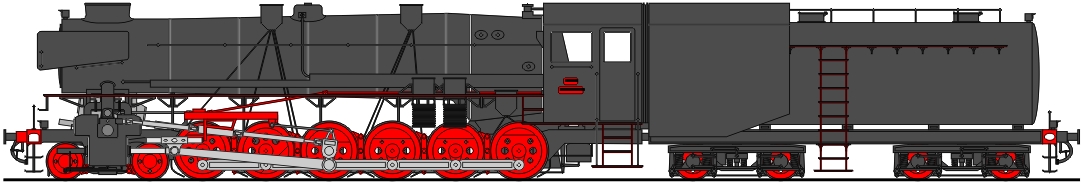
Class 640A 4-Cylinder Fireless Shunting Locomotive (1998)
The quest to find a replacement for the ageing class 520A shunters gave rise to various designs, including the bizarre machine shown here, which was another creation of the RSR design staff in their "spare time". The synchronised opposed piston arrangement, which was inspired by the work of the American engineer Bill Withuhn for the ill-fated ACE3000 Project of 1980, was intended to eliminate dynamic augment ("hammer blow") in fast-running main line locomotives, so what use it should have been to a shunting engine is not clear. Although a prominent feature of the ACE 3000, however, inside coupling rods as such were used in several earlier designs, notably the French PLM class 151A 4-cylinder compound 2-10-2s of 1932. The choice of Walschaerts valve gear seems logical in view of the engine's intended low speed, however. The steam reservoir was intended to be pressed to 1500 lbs/sq in, which would be reduced to the working pressure of 180 lbs/sq in by a normal reducing valve. Needless to say, the engine was never built, its complicated mechanism being quite unnecessary in a mere shunting locomotive.
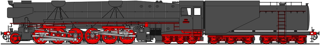
Class 115A Triple-Expansion Compound Beyer-Garratt Goods Locomotive (2005)
A member of Gorote's team, taking advantage of access to the department's computer systems that is granted staff for self-inspired work, produced this design (more a sketch, really) during his spare time. The engine units were taken virtually unchanged from the Ketterik 555A, but with Bulleid-type driving wheels substituted. The boiler was derived from the same engine but shortened and fattened Garratt-style, with a far greater emphasis being placed on direct fire contact at the expense of a proportionately much smaller tube heating surface. The distance between the boiler and the cylinders would make intermediate superheating impractical; on the other hand a higher degree of primary superheat would compensate for potential heat losses in the long steam pipes. The water tanks, tailored to match the smokebox, hail from the 164A and the coal bunker is clearly inspired by the Vanderbilt tender. Various details are not finished or missing, for example the motion brackets, reversing gear and sandboxes.
It's hard to imagine this engine ever being built but if it were, European buffing and drawgear would surely be taxed by the resulting tractive effort of some 60 tonnes (assuming the RSR's maximum axle load of 24 tonnes is exploited to the full). The mile-long trains the engine would be capable of pulling would cause unheard-of line occupancy problems and the firebox's voracious appetite could not be satisfied for long by the relatively small amount of coal that would fit into the bunker.
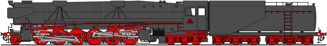
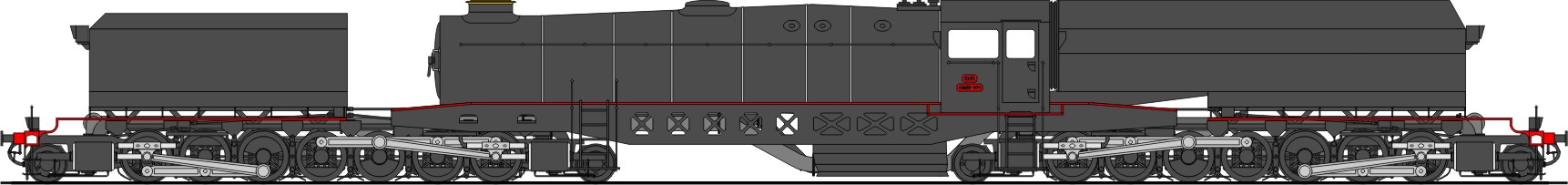
Class 665A Triple-Expansion Compound Express Goods Locomotive (2005)
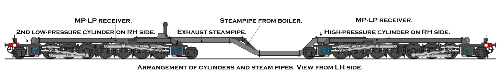
For all the efficiency of the 5-cylinder compound drive that Ketterik so successfully derived from the original Doherty layout, there still remains the problem of balancing the reciprocating masses, which hangs over the entire design effort like the speed of light over space travel. In recent years, the RSR design team, under the skilled leadership of Artur Gorote, has accorded the problem first priority and sought to design the locomotive around a properly-balanced chassis. Over the years, there have been many attempts to improve the balancing of the classical piston engine, the most popular of which was the four-cylinder arrangement, in which each inside cylinder of the locomotive balanced an outside one. With a three-crank arrangement this option is not available. The next option, which was copied from the 640A proposal of 1998, was to mount two outside cylinders on each side, set at 180° to each other, which perforce requires two sets of driving wheels. To avoid the problems of the duplex drive, these are kept in synchronisation by means of inside coupling rods. When the pistons on one side of the engine are at top and bottom mid-stroke, those on the other side are at front and back dead centre, respectively. Thus, on each side of the engine, there are always one piston moving forwards and one moving backwards, providing perfect balancing of the reciprocating masses. To this was added the three-crank drive, the inside cylinders driving the second and fifth coupled axles, respectively.
There is still one matter that the above design has not yet fully addressed: The locomotive is to be a triple-expansion compound. The assignment of the cylinders to each stage of expansion seems at first glance to be straightforward: high-pressure, inside front; medium pressure, outside front; low pressure, all rear cylinders. However, while the inside crank of the two-stage front engine is at 135° to the outside ones, the entire rear engine works at low pressure and thus, within itself, with simple expansion. For such a drive, all cranks should ideally be set at 120° to each other, however this is not possible with quartered outside cranks. The option of the 135° setting on the rear engine unit was still under investigation when the 655C (see below) was conceived.
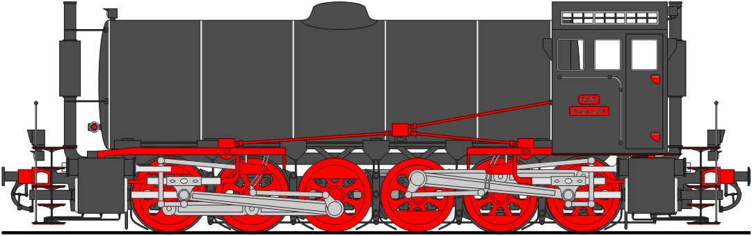
Class 655C Triple-Expansion Compound Express Goods Locomotive (2006)
The RSR's first attempt to use two drive units, synchronised by means of Withuhn inside coupled rods, was doomed to fail because of the conflict over the crank settings for the rear unit. The problem stemmed, in fact, from the illogical assumption that the locomotive had to have six cylinders. Since, however, the 665A was originally designed to eliminate the unbalanced reciprocating masses of the 655B, with its tandem outside cylinders, it was soon realised that a solution could be found in relocating only the low-pressure outside cylinders to the rear of the chassis and that only these were needed to balance the medium-pressure cylinders at the front. Since the low-pressure cylinders are larger than the medium pressure ones, the front outside motion was deliberately made heavier to achieve the same mass at front and rear. The balancing of the front inside high-pressure cylinder was achieved by counterbalance weights on the crank webs. The dynamic augment was considered acceptable since any unresolved reciprocating forces took effect along the centre line of the engine and did not cause any hunting motion. Even if this solution proves to be acceptable, there will still be other objections to the engine's construction. One of these concerns the placing of the cylinders in front of the firebox. Beside engineers' well-known reluctance to expose cylinders and valve gear to the inevitable heat and dirt, the main problem would be the extremely long rear overhang. The tender coupling would be able to keep the locomotive's rear end steady at speed but the lateral displacement of the cab would certainly exceed the loading gauge on all but the most generous curves unless the cab sides were steeply tapered inwards.
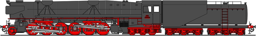
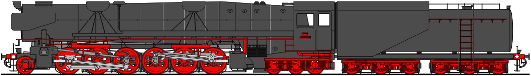
The decision to build a 655C was held back in part by reservations about the long rear overhang and its possible infringement of the loading gauge on sharp curves. In an attempt to obviate this problem, a new rear cylinder block of minimum length was designed, allowing the boiler to be moved forwards and saving some 43 cm. While the decision on the 655CC was still open, the design team produced a further variation on the theme, actually shortening the boiler by 43cm and leaving the smokebox unchanged:
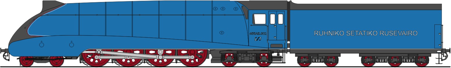
Class 455AB
5-Cylinder
Triple-Expansion Compound Express Passenger Locomotive (2012)
The success of the Nostalgia Expresses led also to a number of streamlining projects based on European designs. One such was the A4-styled 455AA shown here. The main reason why the 455AB never got off the drawing board was that the streamlining of the A4 was integral to the design and not added as an afterthought like that of the NYC J3a. The smokebox of the 455A simply could not be fitted under the sloping front of the A4. The scheme shown here, as attractive as it may have been, would have needed to combine the boiler of the 434A with the chassis of the 455A, requiring a rebuild of the locomotive and a clearly unjustifiable expense for the purposes of "mere" publicity.
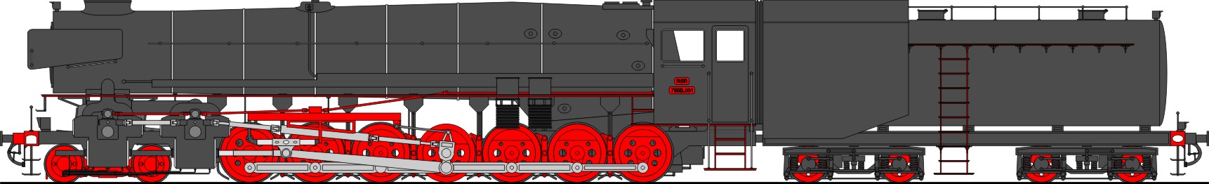
Class 755B 5-Cylinder Triple-Expansion Compound Goods Locomotive (2013)